

Expanding Your 6800 Series System: Controller Interfaces for Synchronized Data Acquisition
Synchronized Data Acquisition Series, Part 2
In Part 1 of this series, we showed why the most valuable test data is connected data. Force and displacement tell you how a specimen responds to load. Signals such as temperature, voltage, resistance, and continuity help explain why. Their full value appears only when every measurement shares one timeline.
This article covers the hardware that makes that possible on an Instron® 6800 Series universal testing system. The controller already installed in your frame offers several ways to add sensors, increase channel count, share signals with other equipment, and coordinate external instruments. The first step is understanding what each interface does.
Key Takeaways
- Every 6800 Series controller has five internal slots. One is dedicated to the primary load-cell Sensor Conditioning Module (SCM). Another is a dedicated encoder slot for used for select strain measurement devices. The other three accept optional SCMs, and one of them can hold an I/O board instead.
- SCMs bring strain and voltage-based measurements into the test, allowing data from sensors, ohmmeters, controllers, and other devices to be synchronized with force and displacement at up to 5 kHz.
- An external Expansion Channel Module adds 4 or 8 SCM channels, for a maximum of 13 SCMs per system, or 12 with an I/O board installed.
- The I/O board provides four 10 V analog outputs, four digital inputs, and four digital outputs.
- Combined with TestProfiler in Bluehill® Universal software, digital I/O can coordinate external instruments at each step of a test method.
What Is Built Into Every 6800 Series Controller?
Every 6800 Series controller shares the same core architecture and standard controls. These built-in functions operate the frame, acquire force and displacement data, and communicate with Bluehill Universal software.
The controller also contains five internal slots for modules:
- Force slot: the primary load cell SCM (dedicated)
- Encoder slot: a channel used to connect strain measurement devices such as the AVE3 Advanced Video Extensometer or AutoX750 Automatic Contacting Extensometer (dedicated)
- Three optional SCM slots: additional SCMs for sensor measurements, or two SCMs and one I/O board
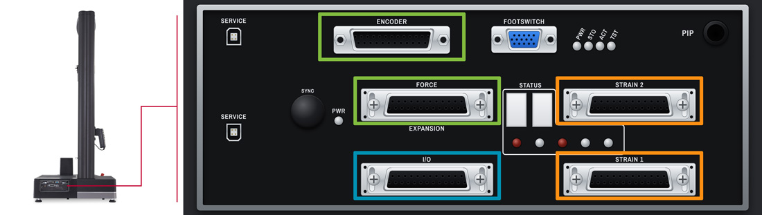
This common architecture gives you a flexible starting point. You can configure the controller around your priority: more sensor measurements, integration with external equipment, or both. Beyond the four internal slots, the system also supports an external Expansion Channel Module and compatible digital encoder devices.
Add Sensor Measurements with Sensor Conditioning Modules (SCMs)
An SCM conditions the signal from a compatible sensor. It converts that signal into a measurement channel that the controller and Bluehill Universal software can use.
Depending on the module, sensor, and system configuration, SCMs can support measurements including:
- Strain
- Temperature
- Voltage
- Pressure
- Additional displacement
Why It Matters
The value is not more data. It is synchronized data. Signals acquired through SCMs share the same timeline as force and displacement. The 6800 Series supports simultaneous data acquisition at the PC at rates up to 5 kHz on force, displacement, and SCM channels.
This lets you correlate a sensor response directly with the mechanical behavior of the specimen. You no longer need to record temperature or voltage on a separate instrument, then merge and align the files after the test. As we covered in Part 1, manual alignment can introduce variation that comes from the analysis process rather than the specimen.
For strain measurement, explore our range of extensometers.
Add More Channels with an Expansion Channel Module
Three optional controller slots cover many applications. Others need more sensors, or the flexibility to add measurements as a test method evolves.
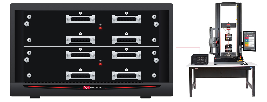
Once the optional controller slots are occupied, an external Expansion Channel Module adds SCM capacity. It is available in four-channel and eight-channel configurations. The module provides a separate enclosure for additional SCMs and stays connected to the 6800 controller and Bluehill Universal software.
How Many Channels Can a 6800 Series System Support?
The total depends on the size of the Expansion Channel Module and whether you install an I/O board. Each count includes the primary load-cell SCM:
- Without an I/O board: up to 9 SCMs with a four-channel module, or 13 SCMs with an eight-channel module
- With an I/O board: up to 8 SCMs with a four-channel module, or 12 SCMs with an eight-channel module
Why It Matters
External SCMs remain part of the same synchronized acquisition architecture. You can grow from a standard force and displacement test to a multichannel measurement system without creating disconnected datasets. This gives you a scalable path to:
- Monitor several aspects of specimen behavior in the same test
- Compare measurements from multiple sensors or specimen locations
- Add channels as an application or test method changes
Share Signals and Coordinate Equipment with the I/O Board
The optional I/O board combines two types of interfaces in a single module.
Analog Outputs
The I/O board provides four zero-suppressed and scaled 10 V analog outputs through BNC connectors. These outputs send Instron measurement signals to external recording, data acquisition (DAQ), or control systems.
This is useful when your lab already runs an external DAQ or proprietary platform that must collect force, displacement, or another Instron signal as part of a broader workflow.
Digital Inputs and Outputs
The I/O board also provides a recorder pulse drive, four digital inputs, and four digital outputs through a 25-pin connector. The digital lines let the testing system exchange changes of state with external equipment:
- A digital output tells another device to perform an action.
- A digital input tells the testing system that an external condition has been met.
Typical uses include:
- Triggering an external DAQ or imaging system
- Receiving a ready or complete signal from another instrument
- Exchanging test status information with a programmable logic controller (PLC)
A later article in this series will cover the events and actions you can assign to digital input and output states.
Automate Multi-Instrument Tests with Digital I/O and TestProfiler
Digital I/O delivers its full value when paired with TestProfiler in Bluehill Universal software. You can configure digital inputs and outputs at different steps in a test method. The signals sent to connected equipment, and the system's response to incoming signals, can change as the test progresses.
For example, within one test method the system can:
- Send a signal to start an external instrument.
- Wait for confirmation that the instrument is ready before continuing.
- Trigger data acquisition or change the state of another device later in the test.
The system can also initiate different actions based on the current test step or whether defined conditions have been met.
Why It Matters
Operators no longer need to start, stop, or reconfigure each device by hand. This simplifies complex workflows, improves consistency, and helps ensure external measurements and actions occur at the correct point in the mechanical test. It also removes the manual steps that, as Part 1 described, create opportunities for missed readings and mismatched specimens.
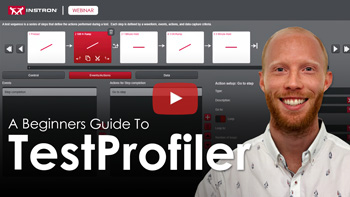
See how events and actions let a test respond to sensors and trigger conditional behavior, the same capability that coordinates digital I/O in this article. Watch to learn the basics, hear example ASTM and ISO applications, and find out if TestProfiler fits your testing needs.
Connect Compatible Encoder-Based Devices
The controller also includes an interface for compatible digital encoder devices. This provides another path for adding measurement devices that communicate through an encoder signal rather than a conventional SCM input.
How to Choose the Right Interface
Start with the test objective, then match it to the interface:
- SCM: Bring a compatible sensor measurement directly into the synchronized test.
- Expansion Channel Module: Add SCM channels when the optional controller slots are occupied.
- I/O board analog outputs: Send Instron measurements to an external acquisition, recording, or control platform.
- I/O board digital inputs and outputs: Exchange triggers, status signals, and changes of state with external equipment.
- Digital encoder interface: Connect compatible encoder-based devices.
Before you configure, answer these questions:
- What additional measurement would provide deeper insight when correlated with force and displacement?
- Does an external device need to be controlled at different stages of the test?
- Should the test wait for a response from another instrument before it continues?
- Does an Instron measurement need to be shared with another acquisition system?
Once the objective is clear, the right interface becomes easier to identify.
Expand the System You Already Have
You may not need a new testing frame to add measurement, integration, or automation capability. The controller in every 6800 Series frame already provides several expansion paths: SCMs for sensors, an Expansion Channel Module for more channels, analog outputs for sharing signals, and digital I/O with TestProfiler for coordinating instruments.
Every measurement acquired through the controller stays synchronized with force and displacement. You expand what you measure and keep the common timeline that makes the data valuable.
Frequently Asked Questions
Synchronized data acquisition captures force, displacement, strain, and additional sensor or instrument data on one common timeline during a test. This lets engineers tie events such as a resistance change or loss of continuity to an exact load and displacement.
Explore Instron Solutions for Synchronized Data Acquisition
From sensor conditioning to expansion channels and digital I/O, Instron has the tools to bring more of your test environment onto one synchronized timeline.

Add synchronized sensor inputs like extensometers, LVDTs, and load cells directly into your digital signal processor for closed-loop strain control.

Scale up to eight channels of signal conditioning and control on 6800 Series systems, monitoring signals simultaneously with no performance loss.

Coordinate external equipment with Bluehill Universal software on 6800 Series systems, triggering and monitoring up to four input and output channels.
or

Talk to an Instron Expert
Not sure which setup fits your application? Our team can review your current configuration and recommend the modules, sensors, and Bluehill Universal software setup to synchronize your measurements.
Contact Our Sales Department
Please complete the form below and we will be happy to contact you with a response. Our typical response time for an online request is within 1–2 business days. For a faster response, please call +1-800-473-7838.

About the Author

Phil Levesque
Phil Levesque is Instron's Electronics Market Manager, with over 13 years of experience in materials testing across engineering and market development. As a former Principal Engineer, Phil led a wide range of projects spanning custom fixture design, automation, and application development for Instron's universal testing systems — building a deep understanding of the challenges and requirements unique to the electronics and semiconductor industries. Today, he applies that hands-on expertise to help customers develop testing strategies that keep pace with the rapid innovation reshaping the market.